
Search This Supplers Products:industrial videoscope manufacturerjoystick borescopesRVI inspection instrumentNDT equipmentwifi borescopeIR videoscope
Power Plant Inspection Camera: Turbine, Boiler & Generator NDT Guide | JEET
time2026/08/14
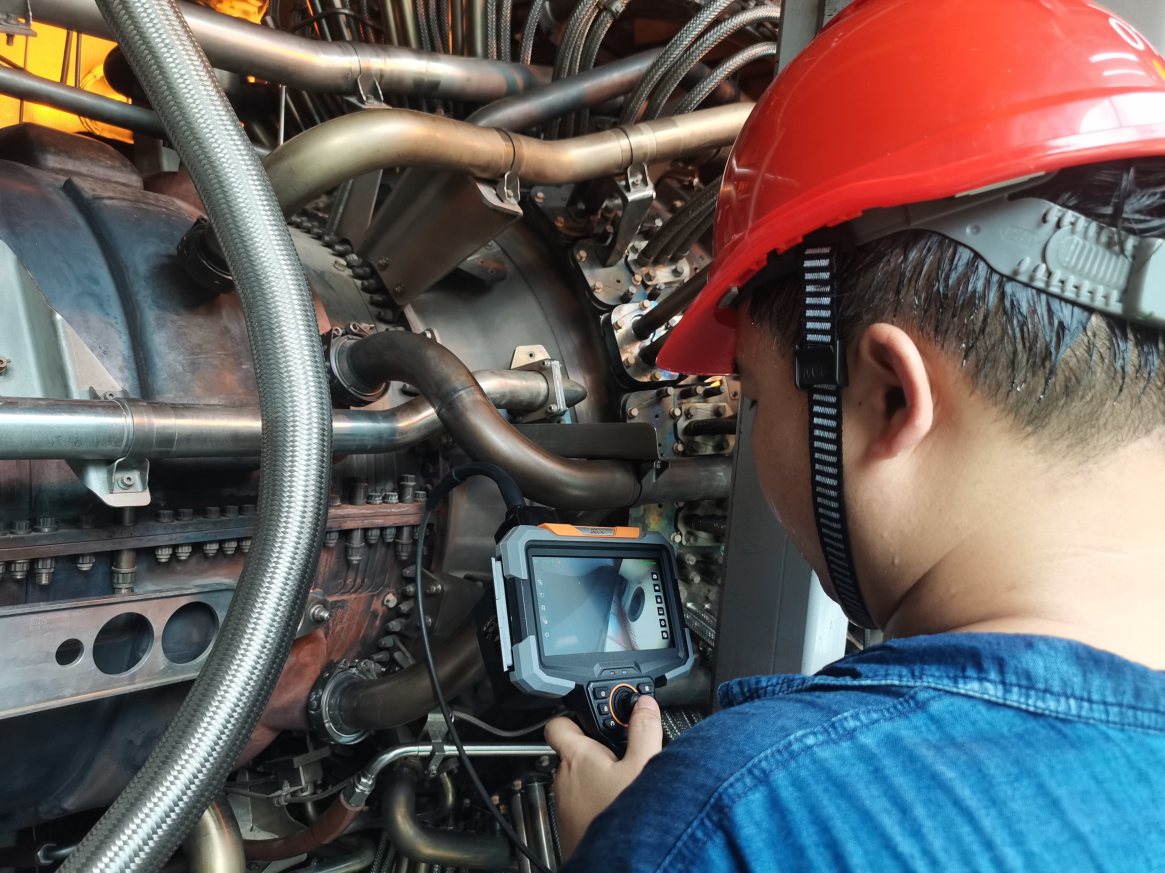
- Field guide to power plant inspection cameras for steam turbines, gas turbines, boiler tubes, generator stators, and wind turbine gearboxes. Covers ASME/EPRI/NRC compliance, 6-step outage workflow, probe specs for extreme environments, and predictive maintenance integration.
A 600 MW steam turbine drops a last-stage blade at 3 AM. The unit trips, the grid loses 600 megawatts in seconds, and the plant enters a forced outage that will last 14 days and cost $3.5 million in lost generation alone — before you factor in replacement power, repair labor, and the regulatory fallout. That blade didn't fail without warning. Erosion pitting, fatigue cracks, and foreign object damage had been accumulating for thousands of operating hours, visible to anyone with a power plant inspection camera who knew where to look. The question is whether your inspection program would have found it.
This guide is for reliability engineers, outage planners, and NDT coordinators who need to deploy borescope inspection across the full spectrum of power generation assets — from fossil-fuel steam turbines and gas turbines to wind turbine gearboxes, boiler tube bundles, and hydroelectric runners. We cover the six highest-risk inspection zones, the equipment specifications that survive extreme plant environments, the ASME and EPRI compliance frameworks that govern your documentation, and the digital workflow that turns inspection images into a trendable asset integrity database. Whether you are preparing for a planned outage or building a condition-based maintenance program from scratch, the guidance below reflects what actually happens on the turbine deck — not the brochure version. For a broader overview of industrial borescope types and specifications, this article complements that resource by focusing on power generation applications.
1. Why Borescope Inspection Is Mission-Critical in Power Generation
Power generation facilities operate under extreme conditions of temperature, pressure, and cyclic loading that degrade critical equipment over thousands of operating hours. A single unplanned turbine trip can cost $1.2–$2.1 million in lost generation margin on a 500 MW unit — and that figure does not include the cost of replacement power, regulatory reporting, or the reputational damage of a grid reliability event. Borescope inspection is the primary NDT method for internal surfaces and components that cannot be examined without full disassembly, and it is often the only practical way to inspect the thousands of tubes inside a boiler, the blade paths inside a turbine, or the windings inside a generator stator.
The shift from time-based maintenance to condition-based maintenance has made remote visual inspection (RVI) not just a compliance activity but a core data source for reliability engineering. Modern power plant inspection cameras don't just capture images — they produce timestamped, location-tagged, defect-annotated data that feeds directly into your CMMS, your risk-based inspection (RBI) program, and your remaining-life calculations. An inspection that produces no trendable data is an inspection that wasted an outage window.
92%
of turbine blade failures are predictable with timed NDT and erosion tracking (EPRI turbine reliability benchmark)
8,000 hr
standard borescope inspection interval for base-loaded steam turbines per ASME PTC 6 guidance — cycling units should halve this
$2.1M
average cost of a single avoided forced outage on a 500 MW unit — one borescope finding pays for the equipment many times over
The outage principle: In power generation, the inspection window is finite and expensive. A planned outage costs $50,000–$200,000 per day in lost margin alone. Every hour spent on borescope inspection must produce defensible, comparable, and actionable data. The right equipment and workflow don't just find defects — they compress the inspection timeline and extend the interval to the next outage.
2. Six Critical Inspection Zones in a Power Plant
Power generation assets span fossil, nuclear, and renewable technologies — each with distinct failure modes, access constraints, and inspection protocols. The six zones below represent the highest-risk areas where borescope inspection delivers the greatest impact on safety, efficiency, and outage economics.
3. Equipment Specs for Extreme Plant Environments
Power plants present some of the harshest operating conditions for inspection equipment: residual heat in turbine casings (80–150°C even after cooldown), oil-immersed gearbox interiors, high-radiation zones in nuclear plants, confined spaces in generator stators, and wet environments in hydroelectric draft tubes. Not every borescope will survive these conditions — and a probe that fails mid-inspection during an outage window can cost a day of lost generation.
| Specification | Steam / Gas Turbine | Boiler Tubes | Generator / Wind / Hydro |
|---|---|---|---|
| Probe diameter | 4–8 mm (access port dependent) | 3–6 mm (curved) / 13–25 mm (push, straight) | 2.8–8 mm (stator: 2.8–6 mm) |
| Working length | 3–7 m | 20–40 m (push camera) | 1.5–5 m (wind blade: 10–30 m) |
| Articulation | 4-way or 360° electric | Fixed head (push) / 4-way (curved) | 4-way or 360° |
| IP rating | IP54 minimum (dust); IP67 if washing required | IP67 (residual water, washdown) | IP67 (oil-immersed gearbox, wet hydro) |
| Tip temperature tolerance | 80–150°C (residual casing heat) | Ambient (inspected post-cooldown) | Ambient; nuclear: radiation-hardened probe |
| Measurement module | Essential (erosion chord loss, crack length) | Recommended (wall loss trending) | Recommended (cavitation depth, insulation degradation) |
| Special considerations | Thermal-resistant tip; high-intensity LED | Push camera rod must resist kinking at bends | Non-metallic tip for stator; portable battery for wind nacelle |
High-Temperature Turbine Environments
Even after a controlled cooldown, steam turbine casings retain residual heat of 80–120°C at the access port. Gas turbine combustor inspections may encounter 120–150°C near the transition pieces. Standard CMOS sensor packages degrade above 80°C. If you are inspecting before full cooldown, select a probe with a thermal-resistant tip sheath and confirm the manufacturer's maximum operating temperature rating. Never insert a probe into a casing above the manufacturer's rated temperature — sensor damage is immediate and irreversible.
Nuclear Radiation Considerations
For nuclear plant inspections (conventional island steam turbine, reactor vessel internals), standard CMOS sensors suffer radiation-induced pixel damage above approximately 10 Gy cumulative dose. Radiation-hardened probes with optical fiber image guides (fiberscope technology) or shielded CCD sensors are required for high-dose areas. The primary advantage of remote visual inspection in nuclear environments is dose reduction for personnel — the borescope allows inspection of activated components from behind shielding, keeping collective dose As Low As Reasonably Achievable (ALARA) per 10 CFR 20.
4. A 6-Step Outage Inspection Workflow
A power plant outage is a tightly choreographed event where every hour of inspection time costs thousands of dollars in lost generation margin. The workflow below is designed to maximize inspection coverage within a constrained window, produce documentation that satisfies ASME and EPRI requirements, and generate data that feeds directly into your CMMS for long-term trending. This is the same structured approach used by outage NDT teams at fossil, nuclear, and renewable facilities.
Outage planning and inspection scope definition
Before the outage begins, define the inspection scope based on operating hours since last inspection, OEM lifecycle curves, condition monitoring triggers (vibration, efficiency, partial discharge), and findings from the previous outage. Build a task card for each equipment ID specifying: CMLs (condition monitoring locations), acceptance criteria, probe access route, expected defects, and required documentation format. A well-prepared task card compresses the on-platform inspection time by 30–50%.
Unit isolation, cooldown, and access preparation
Verify the unit is properly isolated — LOTO (lockout/tagout) for all energy sources (steam, electrical, hydraulic, pneumatic). Confirm casing temperature has dropped below 80°C for standard probes or below the probe manufacturer's rated temperature. Open access ports and install inspection platforms or scaffolding. For boiler inspections, verify confined space entry permits and atmospheric testing (O2, CO, flammable gas) are complete. For nuclear inspections, verify dose rate surveys and ALARA planning.
Equipment setup, calibration, and baseline capture
Verify probe compatibility with the access port ID. Test articulation full range, camera focus, and LED illumination. If a measurement module is fitted, perform the pre-inspection calibration check using the reference gauge block. Set the system timestamp and confirm audio recording is enabled — verbal location annotations on the audio track are the fastest way to document CML positions during fast-moving outage inspections. Insert a clean, dry probe to capture a baseline image before entering the inspection zone.
Systematic coverage with continuous video and defect capture
Record continuously from probe insertion to withdrawal. Follow the task card survey path — for turbine blade paths, sweep from HP through IP to LP stages, noting stage and blade position verbally. For boiler tubes, enter each tube by row and column number. When a defect is found, freeze the frame, apply measurement annotations, and save both annotated and raw images. Classify each finding: erosion, cracking, corrosion, FOD, deposit, or mechanical damage. Record the location reference (stage number, blade position, tube row/column, clock position).
Comparison with prior outage data and erosion rate calculation
If this is a repeat inspection, pull the previous outage's images and measurements for the same CMLs. Compare current findings against historical data at identical locations. Calculate the degradation rate — for example, erosion chord loss per 1,000 operating hours (mm/kh) for turbine blades, or corrosion rate (mm/year) for boiler tubes. Flag any finding that represents a significant rate increase or a new defect type not present in prior inspections. These flags trigger re-evaluation of the inspection interval and remaining-life calculation.
Report generation, disposition, and CMMS upload
Compile the inspection report: equipment ID and tag number, inspection date, inspector name and certification level (ASNT SNT-TC-1A or equivalent), inspection method and applicable standard, all findings with annotated images and location references, degradation rates (if repeat inspection), disposition for each finding (accept / monitor / repair / replace), and recommended next inspection date. Upload the report package (PDF report + image/video files) to your CMMS or inspection data management system. If your borescope supports AI-assisted defect detection, the MDI (maintenance data interface) report can be auto-generated with defect classification tags, further reducing report compilation time.
Outage tip: The most common failure of outage borescope inspection is not missing a defect — it is finding a defect and not being able to find it again at the next outage. Building a standardized location referencing system (stage-blade-clock or tube-row-column) and enforcing it across every inspector and every outage cycle is the single highest-ROI process improvement you can make. Without it, your inspection data is a photo album. With it, your inspection data is a remaining-life database.
5. ASME, EPRI, NRC & IEC Compliance Framework
Power plant inspection is not optional — it is a legally mandated activity governed by a web of codes and standards that vary by plant type, jurisdiction, and equipment class. The borescope images and reports you produce are not just engineering records; they are compliance evidence that regulators, insurers, and OEM warranty programs can request at any time. Understanding which standard applies to which asset is the first step in producing defensible inspection documentation.
ASME Section XI (Nuclear)
- In-service inspection (ISI) program for Class 1, 2, and 3 components
- Section V Article 9: visual testing (VT) acceptance standards
- Examination categories for reactor vessel, piping, pumps, valves
- Inspector qualification: ASNT SNT-TC-1A Level II minimum
- 10-year ISI interval program with cumulative monitoring
- Documentation must support NRC inspection audits
EPRI Guidelines (Fossil & Nuclear)
- Steam turbine borescope inspection guidelines (EPRI TR products)
- Boiler tube failure prevention and root cause analysis
- Generator inspection recommendations (stator, rotor)
- Turbine blade erosion and fatigue assessment methodology
- Non-OEM repair guidance and weld inspection criteria
- Not legally mandatory but adopted by most U.S. utilities
NRC 10 CFR 50 (Nuclear)
- Appendix B: Quality Assurance Criteria for nuclear facilities
- In-service testing of pumps and valves (IST program)
- 10 CFR 50.55a: ASME Code application requirements
- Maintenance Rule (10 CFR 50.65): performance monitoring
- Inspection reports auditable by NRC resident inspectors
- Radiation dose tracking per 10 CFR 20 (ALARA)
IEC 61400 & API Codes (Wind / Fossil)
- IEC 61400-24: wind turbine lightning protection verification
- IEC 61400-5: wind turbine blade structural testing
- API 510: pressure vessel inspection (fossil boilers)
- API 570: piping inspection code (process piping)
- API 580/581: risk-based inspection (RBI) methodology
- ASME B31.1: power piping code (weld inspection)
⚠️ Common compliance gap: Many fossil plants log "borescope inspection completed — no significant findings" in their CMMS without attaching the actual images, CML references, or acceptance criteria. An insurance auditor or NRC inspector will ask: "Show me the image from this blade at the last three outages, with the erosion measurement and the acceptance basis." If you cannot produce a side-by-side trending comparison, the inspection does not meet the documentation standard — regardless of whether the inspection itself was technically competent.
6. Predictive Maintenance & CMMS Integration
The shift from time-based to condition-based maintenance is the single most impactful trend in power plant reliability engineering. Borescope inspection data — when properly structured, stored, and trended — is one of the richest data sources for this transformation. The challenge is not capturing images; it is converting thousands of inspection images into a machine-queryable asset integrity database that your CMMS can use to trigger work orders, adjust inspection intervals, and forecast component replacement timing.
✅ What Modern Digital Inspection Enables
- Automated work-order generation when degradation rate exceeds threshold
- Side-by-side image comparison of identical CMLs across outage cycles
- Erosion rate trending (mm/kh) with remaining-life forecasting
- GPS/time-stamped records traceable to specific inspector and equipment
- Cloud-synced reports accessible by remote reliability engineers during outage
- AI-assisted defect classification with confidence scoring (see our AI defect detection guide)
- Auto-population of RBI (risk-based inspection) input data per API 580
⚠️ What Still Requires Human Engineering Judgment
- Accept/reject disposition for novel or ambiguous defect morphologies
- Evaluation of root cause from inspection findings (chemistry, thermal, mechanical)
- Decision to extend or compress the next inspection interval based on trend data
- Assessment of whether a finding requires immediate repair or can run to next outage
- Interpretation of deposits or surface conditions that AI may misclassify
- Judgment on whether probe access limitations affected inspection completeness
CMMS integration tip: The most effective plants we work with have mapped every borescope CML to a specific asset tag in their CMMS (e.g., "ST-1-LP-L0-Blade-12-LE"). When the inspection report is uploaded, the CMMS automatically creates a work order if the degradation rate exceeds the asset's threshold. This closed-loop system — inspection data in, work order out — is the operational definition of condition-based maintenance. It eliminates the gap between "we found a problem" and "we scheduled the repair."
7. Recommended Inspection Camera Models for Power Plants
No single borescope model covers every power plant inspection zone — the probe diameter for a generator stator (2.8 mm) is incompatible with the working length needed for a boiler tube bundle (20+ meters). The three models below cover the majority of power generation inspection scenarios. For a detailed comparison of inspection camera types, see our push camera vs video borescope selection guide.
Planning Your Next Outage Inspection?
Send us your plant type, equipment list, and inspection scope. Our applications engineers will recommend the correct probe diameter, working length, articulation type, and measurement configuration for each asset — and help you build a standardized inspection task card library before the outage window opens.